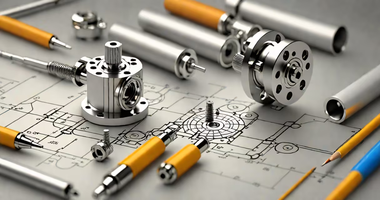
Drafting and engineering is the process of creating detailed technical drawings that communicate design specifications for manufacturing, construction, and other engineering projects. These drawings serve as blueprints for building physical structures, machinery, or products.
Engineering drafting transforms design concepts into precise visual instructions. Engineers and drafters use computer-aided design (CAD) software to create 2D or 3D models. These models include dimensions, materials, and assembly instructions. For example, a mechanical engineer might design a gear system in CAD software, then generate detailed drawings showing each component's size, tolerances, and how they fit together.
Engineering drawings fall into several categories, each serving specific purposes:
| Type | Description | Example Use Case |
|---|---|---|
| Detail Drawing | Shows a single component with all necessary details | A single gear in a transmission system |
| Assembly Drawing | Illustrates how multiple components fit together | A complete engine assembly with labeled parts |
| Section View | Cuts through an object to reveal internal details | Cross-section of a pipe showing wall thickness |
| Isometric Drawing | 3D representation with equal scaling in all axes | Visualizing a complex machine part from multiple angles |
Every engineering discipline relies on drafting. Civil engineers use it to design bridges and buildings. Mechanical engineers draft machinery and vehicles. Electrical engineers create circuit diagrams. Even in engineering fields like biomedical engineering, precise drawings guide the creation of medical devices.
Drafting ensures consistency and accuracy during manufacturing. A single misplaced dimension could lead to costly errors. For instance, Boeing's 787 Dreamliner required over 1 million engineering drawings to ensure every part fit perfectly during assembly.
Many people confuse drafting with general sketching. Unlike freehand sketches, engineering drawings follow strict standards like ANSI or ISO. These standards dictate symbols, line types, and notation conventions. For example, a dashed line always represents a hidden edge, while a solid line shows visible edges.
Another mistake is assuming drafting is obsolete due to 3D modeling. While CAD software has reduced manual drafting, technical drawings remain essential for manufacturing documentation. Even in automated production, workers need clear, standardized drawings to set up machinery and inspect finished products.
The Golden Gate Bridge's construction relied heavily on precise engineering drawings. Chief engineer Joseph Strauss created detailed plans showing every beam, cable, and foundation element. These drawings guided the fabrication of over 80,000 tons of steel and the assembly of 6.8 million rivets. Without accurate drafting, such a complex structure couldn't have been built safely.