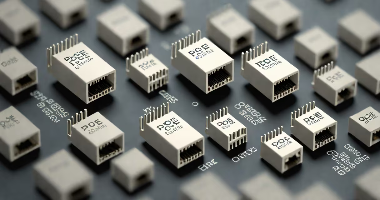
PoE pinout RJ45 specifies which wires in an Ethernet cable carry both data and power for Power over Ethernet (PoE) systems. Standard Ethernet uses four twisted pairs (eight wires) while PoE repurposes unused pairs for DC power.
PoE injects 48V DC alongside data signals using alternate wire pairs. The IEEE 802.3af/at standards define two modes:
Most modern PoE devices support both modes via auto-sensing.
| Mode | Power Pins | Data Pins |
|---|---|---|
| Mode A | 1 (+), 2 (-), 3 (+), 6 (-) | All 8 wires |
| Mode B | 4 (+), 5 (-), 7 (+), 8 (-) | 1-2, 3-6 |
Contrary to popular belief, PoE doesn't require special cables beyond Cat5e or better. Standard Ethernet cables work fine for PoE+ (up to 25.5W) and PoE++ (up to 90W) when properly wired.
One often-overlooked fact: PoE injectors and switches perform power negotiations before sending voltage, preventing damage to non-PoE devices.
For a security camera installation:
Correct PoE pinout prevents voltage drop and ensures reliable power delivery. Improper wiring can cause:
Always verify pin configurations match your PoE devices' specifications.