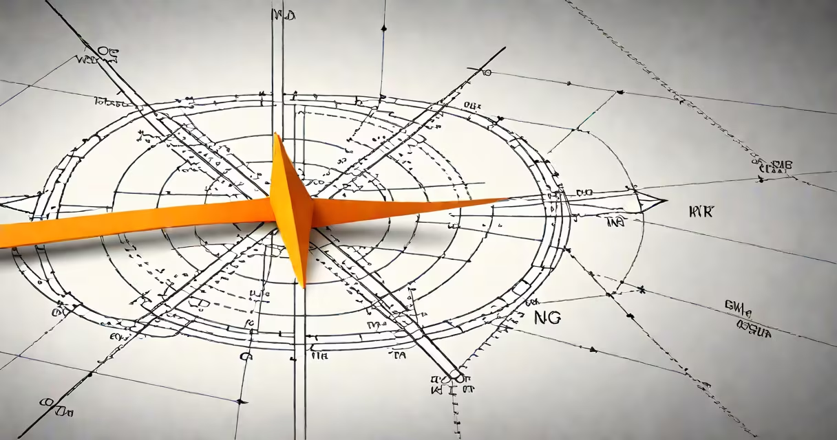
A north arrow DWG is a standardized AutoCAD block that shows map orientation, helping users align drawings with true north. These symbols are essential for site plans, topographic maps, and civil engineering projects.
North arrow DWGs function as reusable symbols inserted into AutoCAD drawings. They contain a graphic representation of an arrow pointing toward magnetic or true north, often accompanied by a label. When placed on a drawing, they provide immediate visual reference for orientation.
North arrows come in various styles and orientations:
| Type | Description | Common Uses |
|---|---|---|
| Magnetic North | Points toward Earth's magnetic field | Site plans, hiking maps |
| True North | Points toward geographic north pole | Surveying, engineering projects |
| Custom Designs | Company-specific or project-specific designs | Corporate projects, specialized applications |
According to the National Society of Professional Surveyors, proper orientation is critical for accurate land measurement and boundary determination. North arrows help prevent costly orientation errors in construction projects.
Many assume all north arrows point to true north, but magnetic north varies by location due to Earth's shifting magnetic field. Some professionals confuse magnetic north with grid north, which accounts for map projection distortions.
For instance, in Denver, Colorado, the difference between magnetic and true north is about 9 degrees, while in Miami, Florida, it's approximately 3 degrees. This variation requires careful selection of the appropriate north arrow type for each project.
To insert a north arrow DWG:
I once worked on a residential development project where we inserted a custom north arrow block that included both magnetic and true north indicators. This helped contractors understand the property's orientation relative to both reference points.