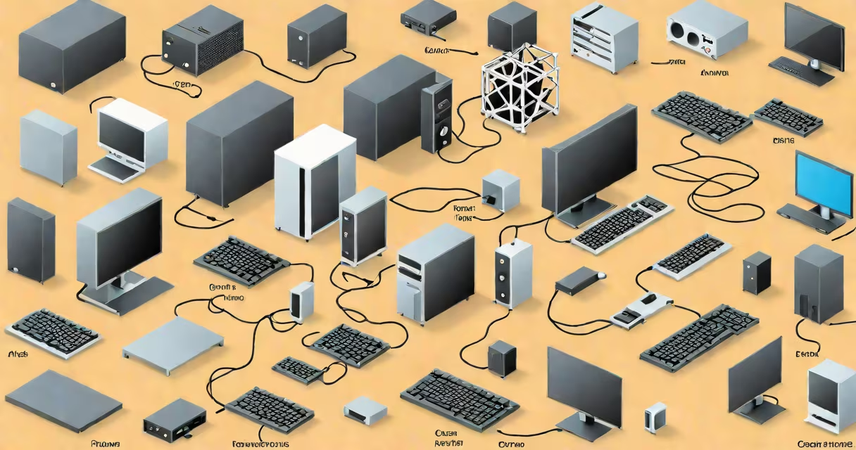
Most diagrams show a side view of an open computer case with components arranged as they appear during assembly. Labels identify each part and often include arrows pointing to connection points between components. Some advanced diagrams may show airflow paths or cable routing suggestions.
The most common parts appearing in diagrams include:
Many diagrams incorrectly show components floating freely rather than mounted to their proper locations. For example, RAM modules should appear inserted into slots on the motherboard, not hovering above them. Another frequent error is omitting essential cables that connect components like the 24-pin ATX power cable from the PSU to the motherboard.
I noticed these issues while creating my first build using a popular online diagram. The diagram showed the GPU disconnected from any power source, which would cause it to fail immediately upon startup in a real system. Always verify diagrams against manufacturer specifications.
Computer diagrams serve several key purposes:
While similar, diagrams and exploded views serve different purposes. Diagrams show components in their actual assembled positions with proper connections. Exploded views separate components to show their individual shapes and mounting points, often used for repair manuals.
| Feature | Computer Diagram | Exploded View |
|---|---|---|
| Component arrangement | Assembled positions | Separated for visibility |
| Connections shown | Yes, with cables | No, components float |
| Primary use | Assembly guidance | Repair reference |
According to Intel's builder resources, proper cable management shown in diagrams can improve airflow by up to 15% compared to tangled cable arrangements. This highlights the practical value of accurate diagrams for system performance.