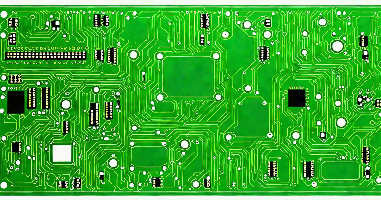
PCB electronics refers to printed circuit boards (PCBs), which are the physical platforms that mechanically support and electrically connect electronic components using conductive pathways etched from copper sheets laminated onto a non-conductive substrate.
A PCB acts as the core of most electronic devices, providing a stable base for components while routing electrical signals between them. The conductive pathways are created through a process called etching, where unwanted copper is removed from a copper-clad board, leaving only the desired traces.
PCBs come in several varieties, each suited to different applications:
| Type | Description | Common Uses |
|---|---|---|
| Single-sided PCBs | Components mounted on one side, with conductive traces on the other | Simple electronic devices like power supplies, calculators |
| Double-sided PCBs | Components on both sides, connected by plated-through holes | More complex devices like amplifiers, industrial controls |
| Multi-layer PCBs | Multiple layers of conductive material separated by insulating layers | High-performance electronics like computers, medical devices |
| Rigid PCBs | Solid, inflexible boards | Most consumer electronics, appliances |
| Flexible PCBs | Thin, bendable circuits | Wearable tech, automotive systems |
The most common PCB substrate material is FR-4, a glass-reinforced epoxy laminate. For high-frequency applications, materials like Rogers RO4350B offer better performance. The manufacturing process involves several steps: designing the circuit layout, printing the circuit pattern onto the board, etching away excess copper, drilling holes for component leads, and finally applying a protective coating.
One non-obvious fact about PCBs is that they often contain solder masks (usually green) to prevent short circuits and silkscreen printing to label components and test points. These features are essential for assembly and troubleshooting but are often overlooked by beginners.
PCBs are ubiquitous in modern electronics, found in everything equipment. They enable compact, reliable designs by allowing components to be interconnected efficiently. For example, a typical smartphone PCB might contain dozens of components, including processors, memory chips, and sensors, all connected through complex traces.
PCBs are often confused with breadboards, which are temporary prototyping tools. Unlike breadboards, PCBs are designed for permanent, reliable connections in finished products. Breadboards are useful for testing circuits before committing to a PCB design.
When designing a PCB, engineers must consider factors like signal integrity, power distribution, thermal management, and manufacturability. High-speed signals require careful trace routing to minimize interference, while power planes distribute voltage evenly across the board. Thermal vias can help dissipate heat from high-power components.
I once designed a simple LED circuit board for a hobby project. I initially overlooked the importance of trace width for current-carrying capacity, which led to overheating. After adjusting the trace widths and adding a heat sink, the circuit functioned correctly. This experience highlighted the importance of careful PCB design.
The field of PCB electronics is evolving with advancements in materials, manufacturing techniques, and design software. High-density interconnect (HDI) PCBs are becoming more common, allowing for smaller, more complex circuits., the integration of flexible electronics and wearable technology is driving demand for flexible PCBs.
For those interested in learning more about the technology behind PCBs, exploring modern electronics engineering can provide deeper insights into the field.